Table of Contents
Low-noise amplifier LNA01A
A low-noise preamplifier module (LNA). The original construction is intended to be used in bands around 143MHz, but it is probable, that it can be used in other bands as well, as the used transistor ATF-53189 shows good characteristics up to approximately 6GHz.
Construction
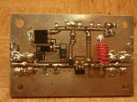
The connection of the amplifier is implemented using the FR4 PCB. It is possible to fit the PCB with straight SMA connectors or edge connectors. The amplifier is expected to be placed inside the metallic shielding box.
The following scheme shows the circuit of the module: LNA01A scheme.
Tuning
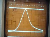
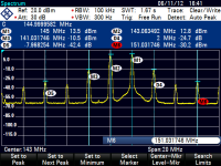
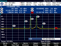
The amplifier tuned to 143MHz band:
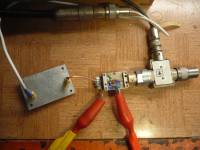
The transmission curve of the LNA01A. Smaller horizontal lines in the upper part of the screen have a scale increment of 10MHz, increment for larger lines is 100MHz and 200MHz. The gain is approximately 27 dB.
A coil performing on 144Mhz has 7 turns of 0.5mm wire around a rod with a diameter of 4mm (a drill). The coil is stretched as seen in the picture. The capacitors C1 and C2 have the capacitance of 8,2 pF. It is not necessary to use a feedback on LNA, as it increases the s/n ratio and decreases the gain by approximately 1dB. A trim is replaced by a 45 Ω resistor and the total current through the LNA should be around 153mA. The current through source transistor is than about 135mA.
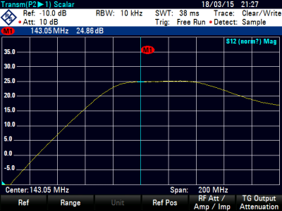
The measured parameters
Applications
This preamplifier is primarily constructed for use in combination with SDR receiver SDRX01B. Its characteristics are optimized for use in radioastronomy or cosmic research.
Covering
The module fits into metallic shielding boxU-AH101
References
- Extra-2 - the original HA8ET construction

