
Table of Contents
General hints for use of MLAB modules
This page sums up the possibilities and means of MLAB modules' use. The individual paragraphs contain various different applications and special cases.
Beginners can make use of a guide for beginners.
Obtaining a module
In order to begin construction, first you have to obtain all the necessary modules - either by building your own prototypes or by buying a ready-made module. In case you do not find the necessary module, you can build it according to rules guaranteeing compatibility.
Tools
Mechanical tools
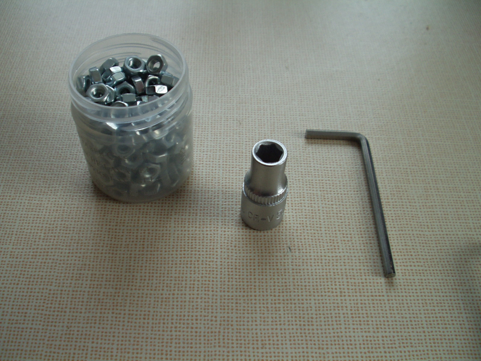
Work with MLAB modules requires only basic mechanical tools: a hexagonal socket wrench 5.5 mm with a knurled edge for tightening using a hand, a hex key (in the case of older models a cross screwdriver), and a lot of M3 nuts.
Electronic tools
Multimeter
A multimeter of almost any type is sufficient, however, we recommend a digital one.

More advanced users can use a table multimeter.
Oscilloscope
An oscilloscope is a very useful tool when tuning any signal system. We use the following Rigol DS1052E, which, in its basic version, is 50MHz, but a firmware change can update it to 100MHz.

Soldering iron
A soldering iron is not necessary for most of the MLAB constructions, it is, however, a good investment for any laboratory. We can recommend Czech micro soldering irons from Sagat company. They have excellent heat power and tips of high quality.

It is even possible to agree on purchasing a 100W version with parameters exceeding even high-class micro soldering irons from Weller.
When soldering pieces like connectors or thick wires and tinned sheet metal boxes, it is more practical to use a transformer soldering iron because of its higher heat power (150W).

When buying a transformer soldering iron, make sure you are buying one with a horizontal soldering tip, as shown in the picture. Transformer soldering irons with vertical tips are more suitable for sheet soldering or welding/cutting plastics.
All types of soldering irons require a tube tin and a flux, otherwise, they will not work properly. For more information see the -blog article chapter about flux
An aid for smoke extraction
During any soldering, the evaporated flux creates a very unpleasant smoke that irritates the respiratory tract. One of the solutions is to build a simple aid from an older PC ventilator. Connect it to an adjustable power supply and set it on a table in a way that it would blow the smoke away from the soldering workplace. In order to reduce noise, the ventilator can be put onto a piece of rubber, for example from an old inner tube of a bike.
Using the tools
Connecting the oscilloscope probe
An oscilloscope’s probe ground can be easily connected to an MLAB kit thanks to the base ALBASE. Most of the modules (with an exception of power supply ones) have corner screws connected to GND. That is why it is sufficient to put a screw from below to the base and screw it with a nut from above. You can use the protruding screw as a ground clamp for the oscilloscope’s probe.
The signal probe input can be connected to MLAB in the following way: the connecting cable is cut in half, part of the cable is stripped of insulation and a crimp pin connector is crimped onto the cable. Now the cable, via the crimp pin connector, can be easily attached to the probe’s hook and its second end with the original PC terminal can be connected to the pinch outlets of all modules.
Connecting of modules
Modules are connected via stranded wires with PC connectors. An advantage of this method is that after cutting the wire, both free ends can have any component soldered onto themselves - e.g. LED, resistor, condenser, interference suppressor, etc. Unprotected ends have to be covered with a shrinking tube. This way you have built a reliable and useful component of the kit.
Power supply
Power provided by power supplies is distributed, among the modules, via cables different from the usual interconnecting ones. Furthermore, they are colored according to the different power voltages, thus reducing the possibility of a fatal mistake during their connecting.
Power supply up to +5V
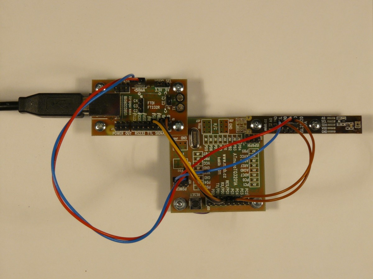
This power voltage is distributed by a red-blue power cable with a three-pin connector.

3.3V
The power voltage of 3.3 V is led by the same cable as the +5V power supply, only the red wire is replaced by an orange one.
Voltage higher than +5V
This category usually involves 7.2 (2x Li-ion cell) or +12V (lead-acid battery or other power supplies). For safety reasons, it is therefore led via a yellow (+) and black (-) cable, following an example of ATX power supplies. Connectors are four-pin, the middle two pins being + and the outer two -/GND. The connector is symmetrical, so the polarity cannot be easily mixed up.

Symmetrical power supply
This kind of power supply, conventionally +12V and -12V, is used in analog constructions, which are using operational amplifiers. It is distributed by power cables with 5 pins - the middle + two pins are positioned symmetrically around the central - pin and the two extreme pins on both sides are GND or chassis.

High voltage power supply
In cases where we work with high currents (up to tens of Amperes) and, at the same time, high voltages (tens of Volts) (a typical example is a robot’s drive powered from an accumulator), the power is distributed via an individual cable with FASTON connectors. Because the protection against polarity reversal is quite problematic in case of high currents, there is a need for increased caution when connecting such constructions.
Very high voltage power supply
It includes power voltage in the range of hundreds of volts to ones of kV. Such power is used for certain special detectors or gas discharge lamps, LASERs, etc. It is distributed via a coaxial cable with SHV or MHV connectors.
High-frequency signals
Asymmetrical signals
Analogue VF signals are distributed in MLAB via a classic VF Pigtail usually made from coax RG-174 with both ends having a screw-type SMA (Male) connector.

Caution the connector in the picture contains a sample error - a missing shrinking tube over a crimped connector ferrule. Without it, there is the gradual breaking of the cable sheet from the connector.
Crimped connectors’ ferrules have to be protected by a shrinking tube! A guide for crimping SMA connectors - in the video guide, the connector is covered by a special sleeve instead of a shrinking tube
Differential symmetrical signals
Fast digital signals, such as those of AD converters’ clocks or sequence circuits, are in MLAB usually distributed differentially in order to limit interference. We usually use PECL or LVDS logic. Signals are led via a standard direct SATA cable - chosen for its defined impedance and good availability.

Digital buses
Digital buses, such as I2C, TWI, or 1-wire are distributed between the modules via standard cables, usually only adjusted so that one plastic end contains all the bus’s wires, possibly together with a power supply.
Maintenance and cleaning
Interconnecting cables
Due to gradual wear by mechanical switching, the interconnecting cables’ connectors lose their conductivity. It lasts several hundreds of connections and re-connections until the phenomenon occurs, but it might be speeded up by a careless transport of already connected constructions, during which the connectors undergo a side strain. (For example when carrying more connected boards thrown one other another in a box). You can reveal this state simply by checking, that the cable pin does not hold onto the pin header with perceptible friction. The above-mentioned state can be repaired by slight deforming of the connector spring by using a screwdriver or other similar tool. The procedure is done from outside at the connector's lock, applying pressure on the spring against a table.
Modules
Most of the modules do not require any additional maintenance. Sometimes it happens, that dust piles up intensively onto modules. It might be solved either by blowing it away with an air blower ball (compressed air) or by brushing it off with an anti-static brush.
It is not possible to use an electrostatic duster for dust removal as it might cause the destruction of certain electronic circuits in modules
When a module is extremely dirty, it can be cleaned with an ultrasonic cleaner. However, there are some modules (sensors, GPS) that might be damaged by this process, which is why it cannot be universally recommended.
External connectors
Connector for switching in other devices.
Power supply
External power supply for MLAB modules is usually led by cylindrical connectors 5.5/2.1 mm to the main powering modules, e.g. UNIPOWER01A.

Cylindrical connectors of different voltages are distinguished using a shrinking tube around a connector - yellow = 12V, red = 5V.
Power supplies may also use a PC standard ATX and MOLEX connector.
In the case of having a power supply supplied only from batteries, it is better to use e.g. BATPOWER02A module. When connecting accumulators, where we expect higher current load, T-connectors are used (the standard cylindrical model-building ones did not work out very well)

General terminal blocks
Screw terminal
There are two widespread types of commonly used screw terminals on the market. Apart from a considerable difference in their costs, they also differ greatly in the quality and convenience of their use.
The first type is more common mostly due to its low price. However, thanks to using a sheet metal washer under screws, it is not possible to fasten a naked wire of a small diameter well into this type of screw terminal. Furthermore, the sheet metal washers often fall out or block the pulling out of the wire.

The second type is more expensive but does not experience the above-mentioned problems. Furthermore, it is possible to fasten even a naked wire. This terminal block guarantees a good quality conductive connection.

Spring terminal block
Spring terminal blocks are an excellent modern substitute for screw terminals, which are slowly becoming technically obsolete. Their disadvantage, in comparison to screw terminals, is a slightly larger size and an impossibility of regulating the compressing of connection.
One of the commonly used spring terminal blocks is WAGO256.

High-frequency signals
High-frequency signals are led to external devices in the same way as they are between modules - via coaxial cables with SMA connectors or they are connected via a short pigtail to some other panel RF connector. Preferred are the following connectors’ types (in a given order): F, BNC, N, and PL.
In order to connect distant devices, such as receiving antennae, F-connector is a good choice, main thanks to its easy assembly and disassembly, allowing for easy placement of coaxial cables.
Data connectors
USB
The most widely found external bus used with modules is a USB with a USB-B connector. A reason for using USB B is that it is the most robust USB connector, it has outlets through the board and thus it does not brake away from PCB (like other variants of USB micro connectors).

Using a USB connector on a module requires placing a current fuse into the charging from USB (usually 750mA PTC). Otherwise, a short circuit can cause a fall of the HOST system and thus a data loss (of a tuned program).
RS-232
Another data connector is D-sub of DE-9 type. We use it mainly for serial data transfer of RS-232 standard.
RS-485
In industry, this bus is used with terminal blocks. Therefore it is practical to use e.g. INPUTUNI01A module.
CAN
To distribute CAN buses over longer distances, for example in buildings, we recommend using UTP cable and RJ-45 connectors.
Test constructions
Standard arrangement
Test constructions consist of one of the base boards.
")
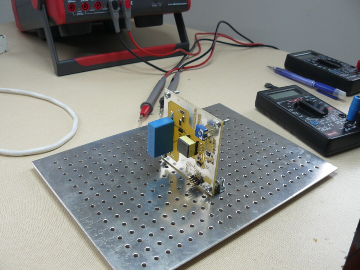
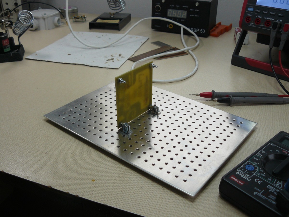
Measuring arrangement
The following way of assembly, when we use structural shapes, for example, from the Merkur building kit, in order to attach the corner screws, has an advantage in that you can access both sides of the board without any problems and carry out measurements also on a PCB. It is thus suitable for reviving new modules.
Direct mounting
Modules can also be screwed directly into each other, a feature advantageous mainly for undemanding constructions made of several modules of similar size.
Tower arrangement
Metal MLAB mounts can be stacked with one another using threaded rods. Such an arrangement saves space and enables the construction of more complicated and large-scale systems.

The threaded rods used in the example are of M5 type and each board is fastened by a nut from above and below. There are washers between the board and the nuts. There is a spring washer used with one of the nuts. The cutting length in the case of two boards above each other is 12 cm. This length was chosen because a 1m threaded rod can be divided into 8 columns and there is 4cm left for cutout and tolerance.
Permanent installations
We can easily construct permanent or semi-permanent installations from the kit by screwing the tuned constructions with the baseboard to the bottom of the junction box. In order to increase the resistance against vibrations we can glue the přívody k hřebíkům (??) with a hot-melt adhesive and tie the cables to the base with a cable tie. Such construction is relatively cheap and, at the same time, robust and adjustable if necessary.
Stand-alone construction
We can easily fit the module construction in the UNIBOX metal box.


Installation into the distribution board
In a similar manner, modules can be installed in the low-voltage parts of distribution boards. You can use plastic clips (??) (available at good electro shops) to attach them to a DIN panel.

Installation into the electrical box
An electrical box can be used in a similar way as a distribution board with one exception - there is usually not any problem with attaching the base board.

Sample construction
- Timekeper - measures the time of movement between several photoelectric sensors (?? optická závora)