
This is an old revision of the document!
Table of Contents
 This page is not fully translated, yet. Please help completing the translation.
(remove this paragraph once the translation is finished)
General hints concerning modules
This pages sums up the possibilities and means of MLAB modules use. The individual paragraphs contain various different applications and special cases.
Beginners can make us of a guide for beginners
Obtaining a module
In order to begin a construction, first you have to obtain all the necessary modules - either by building your own prototypes or by buying a ready-made modules. In case you do not find the necessary module, you can build it according to rules guaranteeing compatibility.
Tools
Mechanical tools
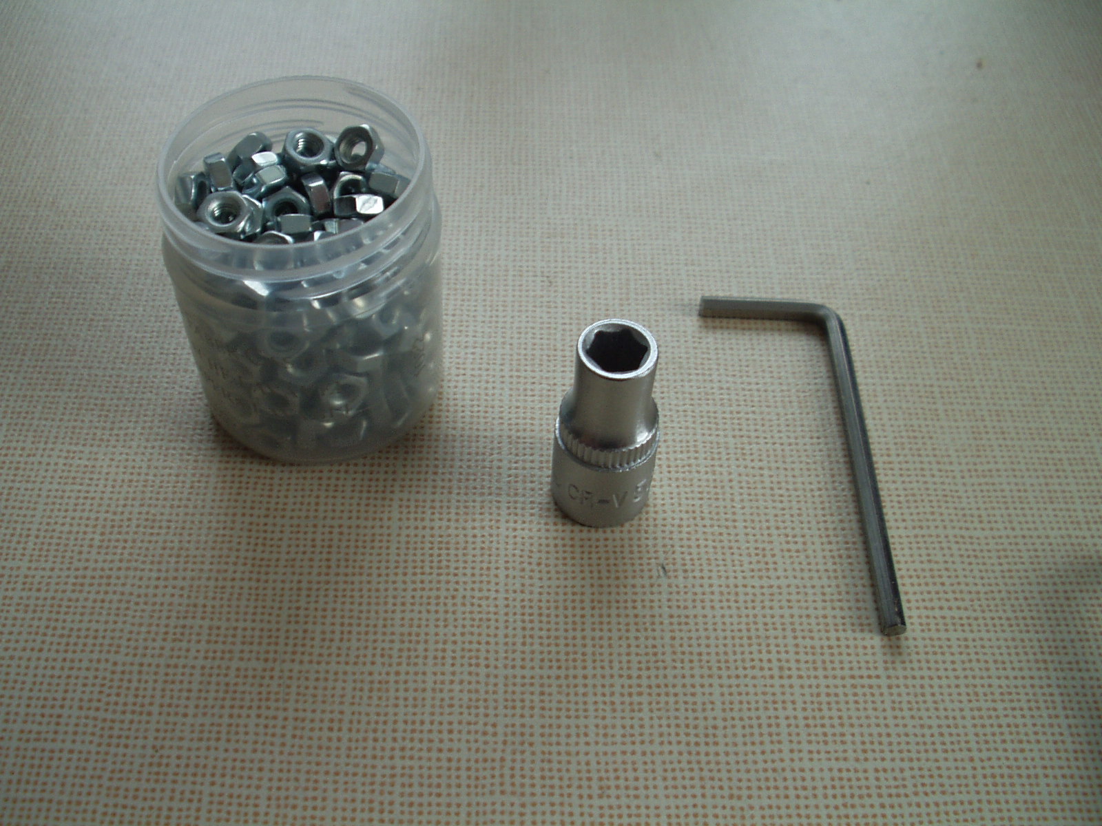
Work with MLAB modules requires only basic mechanical tools: a hexagonal socket wrench bola 5.5 mm with knurled edge for tightening using a hand, a hex key (in case of older models a cross screwdriver) and a lot of M3 nuts.
Electronic tools
Multimeter
Multimeter of almost any type is sufficient, we recommend a digital one.

More advanced users can use a table multimeter.
Oscilloscope
An oscilloscope is very useful tool when tuning any signal system. We use a following Rigol DS1052E, which, in its basic version, is 50MHz, but a firmware change can update it to 100MHz.

Soldering iron
A soldering iron is not necessary for most of the MLAB constructions, it is, however, a good investment for any laboratory. We can recommend Czech micro soldering irons from Sagat company. They have an excellent heat power and tips of a high quality.

It is even possible to agree on purchasing a 100W version with parameters exceeding even high class micro soldering irons from Weller.
When soldering peaces like connectors or thick wires and tinned sheet metal boxes, it is more practical to use a transformer soldering iron because of its higher heat power (150W).

When buying a transformer soldering iron, make sure you are buying the one with a horizontal soldering tip, as shown on the picture. Transformer soldering irons with vertical tips are more suitable for sheet soldering or welding / cutting of plastics.
All types of soldering irons require a tube tin and a flux, otherwise they will not work properly. For more information see chapter flux at http://www.mlab.cz/Articles/HowTo/How_to_make_PCB/DOC/HTML/How_to_make_PCB.cs.html
An aid for smoke extraction
During any soldering, the evaporated flux creates a very unpleasant smoke that irritates the respiratory tract. One of the solutions is to build a simple aid from an older PC ventilator. Connect it to an adjustable power supply and set it on a table in a way that it would blow the some away from the soldering workplace. In order to reduce a noice, the ventilator can be put onto a piece of rubber, for example from an old inner tube of a bike.
Using the tools
Connecting the oscilloscope probe
An oscilloscope’s probe ground can be easily connected to a MLAB kit thanks to the base ALBASE. Most of the modules (with an exception of power supply ones) have the corner screws connected to GND. That is why it is sufficient to put a screw from below to the base and screw it with a nut from above. You can use the protruding screw as a ground clamp for the oscilloscope’s probe.
The signal probe input can be connected to MLAB in a following way: the connecting cable is cut to half, part of the cable is stripped of an insulation and a crimp pin connector is crimped onto the cable. Now the cable, via the crimp pin connector, can be easily attached to the probe’s hook and its second end with the original PC terminal, can be connected to the pinch outlets of all modules.
Connecting of modules
Modules are connected via stranded wires with PC connectors. An advantage of this method is that after cutting the wire, both free ends can have any component soldered onto themselves - e.g. LED, resistor, condenser, interference suppressor, etc. Unprotected ends have to be covered with a shrinking tube. This way you have built a reliable and useful component of the kit.
Power supply
Powering by power supplies is distributed, among the modules, via cables different from the usual interconnecting ones. Furthermore, they are coloured according to the different power voltages, thus reducing the possibility of a fatal mistake during their connecting.
Power supply up to +5V
This power voltage is distributed by a red-blue power cable with a three-pin connector.

3.3V
Power voltage for 3.3 V is lead by the same cable as the +5V power supply, only the red wire is replaced by an orange one.
Voltage higher than +5V
This category usually involves 7.2 (2x Li-ion cell) or +12V (lead-acid battery or other power supplies). For safety reasons it is therefore led via a yellow (+) and black (-) cable, following the example of ATX power supplies. Connectors are four-pin, the middle two pins being + and the outer two -/GND. The connector is symmetrical, so the polarity cannot be easily mixed up.

Symmetrical power supply
This kind of power supply, conventionally +12V and -12V, is used in analogue constructions, which are using operational amplifiers. It is distributed by power cables with 5 pins - the middle + two pins are positioned symmetrically around the central - pin and the two extreme pin on both sides are GND or framing. (kostra ??)

High voltage power supply
In cases where we work with high currents (up to tens of Amperes) and, at the same time, high voltages (tens of Volts) (a typical example is a robot’s drive powered from an accumulator), the power is distributed via an individual cables with FASTON connectors. Because the protection against polarity reversal is quite problematic in case of high currents, there is a need for increased caution when connecting such constructions.
Very high voltage power supply
It includes power voltage in range of hundreds volts to ones of kV. Such powering is used for certain special detectors or gas discharge lamps, LASERs, etc. It is distributed via a coaxial cable with SHV or MHV connectors.
High-frequency signals
Asymmetrical signals
Analogue VF signals are distributed in MLAB via a classic VF Pigtail usually made form coax RG-174 with both ends having a screw-type SMA (Male) connector.

Caution the connector in the picture contains a sample error - a missing shrinking tube over a crimped connector ferrule. Without it, there is gradual breaking of the cable sheet from the connector.
Crimped connectors’ ferrules have to be proteced by a shirnking tube! A guide for crimping SMA connectors - in the video guide, the connector is covered by a special sleeve instead of a shrinking tube
Differential symmetrical signals
Fast digital signals, such as those of AD converters’ clocks or sequence circuits, are in MLAB usually distributed differentially in order to limit interference. We usually use PECL or LVDS logic. Signals are lead via a standard direct (??) SATA cable - chosen for its defined impedance and good availability.

Digital buses
Digital buses, such as I2C, TWI or 1-wire are distributed between the modules via standard cables, usually only adjusted so that one plastic ending contains all the bus’s wires, eventually together with a power supply.
Maintenance and cleaning
Interconnecting cables
Due to a gradual wear by a mechanical switching, the interconnecting cables’ connectors loose their conductivity. It last several hundreds of connections and re-connections until the phenomenon occurs, but it might be speeded up by careless transport of already connected constructions, during which the connectors undergo a side strain. (For example when carrying more connected boards thrown one other another in a box). You can revel this states simply by checking, that the cable sleeve (?? Dutinka kablíku) does not hold onto the pin (?? Hřebínek). The above-mentioned state can be repaired by
U propojovacích kablíků se v důsledku jejich postupného opotřebení mechanickým přepojováním snižuje vodivost jejich konektorů. Trvá řádově několik stovek zapojení, než se tento jev projeví, ale může být urychlen například neopatrnou přepravou zapojených konstrukcí, kdy jsou konektory v desce stranově namáháhy. (například hozených více zapojených desek na sebe v krabici) Tento stav se pozná jednoduše i mechanicky tak, že dutinka kablíku téměř nedrží nasunutá na hřebínku.
Tento stav lze napravit opětovným napružením kontaktu konektoru šroubovákem, nebo jiným podobným nástrojem. To se provádí zvenku u zámku konektoru. tlakem na pružinku proti stolu.
Modules
Most of the modules does not require any additional maintenance. Sometimes it happens, that a dust piles up intensively onto modules. It might be solved either by blowing it away with an air blower ball (compressed air) or by brushing it off with an anti-static brush.
It is not possible to use electrostatic duster for a dust removal as it might cause a destruction of certain electronic circuits in modules
When a module is extremely dirty, it can be cleaned in an ultrasonic cleaner. However, there are some modules (sensors, GPS) that might be damaged by this process, that is why it cannot be universally recommended.
External connectors
Connector for switching in other devices.
Power supply
External power supply for MLAB modules is usually led by cylindrical connectors 5.5/2.1 mm to the main powering modules, e.g. UNIPOWER01A.

Cylindrical connectors of different voltages are distinguished using a shrinking tube around a connector - yellow = 12V, red = 5V.
Power supplies may also use a PC standard ATX and MOLEX connector.
In case of having a power supply supplied only from batteries, it is better to use e.g. BATPOWER02A module. When connecting accumulators, where we expect higher current load, T-connectors are used (the standard cylindrical model-building ones did not work out very well)

Obecné svorkovnice
Šroubové svorkovnice
Na trhu existují dva rozšířené typy běžně používaných šroubových svorkovnic. Kromě toho, že se poměrně výrazně liší cenou, tak se ještě výrazněji liší kvalitou a komfortem jejich užití.
První typ je více rozšířený hlavně kvůli své nizké ceně. Avšak díky použití plechových vložek pod šrouby není možné do tohoto typu kvalitně upnout holý vodič malého průměru. Navíc plechové podložky často vypadávají, případně blokují vytažení vodiče.

Druhý typ je dražší, ale tyto problémy nemá, navíc je možné upnout i čisté lanko. A tato svorkovnice je v podstatě zárukou kvalitního vodivého spoje.

Pružinové svorkovnice
Pružinové svorkovnice jsou výbornou moderní náhradou za šroubové svorkovnice, které technicky již pomalu zastarávají. Jejich nevýhodou o proti šroubovým svorkovnicím je pouze mírně větší rozměr a nemožnost regulace přítlaku spoje.
Používaným typem je obvykle WAGO256

Vysokofrekvenční signály
Vysokofrekvenční signály jsou k externím zařízením v laboratoři vedeny stejně, jako mezi moduly koaxiálními kablíky s SMA konktory. Nebo případně připojeny krátkým pigtailem k některému jinému panelovému RF konektoru. Přeferovány, jsou konektory typu F, BNC, N a PL (v tomto pořadí). Pro připojení vzdálených zařízení, jako například přijímacích antén je dobrá volba F-konektor především díky jeho snadné montáži a demontáži, což umožňuje snadné protahování koaxiálních kabelů.
Datové konektory
USB
Nejrozšířenější externí sběrnicí užívanou na modulech je USB s konektorem USB-B. Důvod použití konektoru USB B je v tom, že je to nejodolnější konektor pro USB, má vývody skrz desku a tím pádem se netrhá z PCB, jako různé další varianty USBmicro konektorů.

Použití USB konektoru na modulu vyžaduje zařazení proudové pojistky do napájení z USB (obvykle 750mA PTC) Protože jinak může při vyzkratování napájení dojít ke shození HOST systému a tím pádem i ke ztrátě dat (laděného programu).
RS-232
Dalším používaným datovým konektorem je D-sub typu DE-9. Je využívaný hlavně pro sériový datový přenos standardu RS-232
RS-485
V průmyslu se se na tuto sběrnici používají svorkovnice. Vhodné tak je použít například modul INPUTUNI01A.
CAN
Pro rozvod sběrnice CAN na delší vzdálenosti, například v domě, je vhodné použít UTP kabel a konektory RJ-45.
Testovací konstrukce
Standardní uspořádání
Testovací konstrukce se skládají na některou ze základních desek.
")
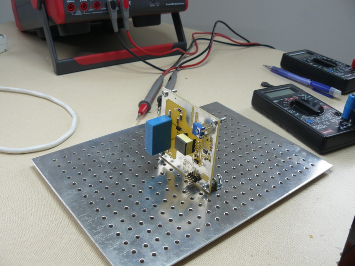
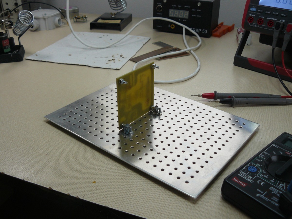
Měřící uspořádání
Tento způsob montáže kdy se na uchycení rohových šroubů modulů využijí úhelníky například ze stavebnice Merkur má výhodu v tom, že lze pak bez problémů přistupovat k obou stranám desky a měřit i na plošném spoji. Proto se hodí zejména k oživování nových modulů.
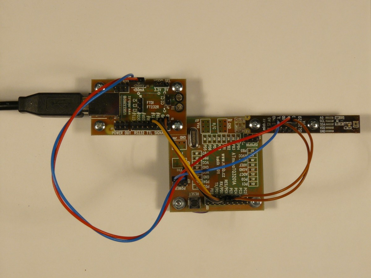
Přímé skládání
Moduly lze také šroubovat přímo k sobě což je výhodné zejména pro nenáročné konstrukce z několika modulů podobné velikosti.
Věžové uspořádání
Kovové MLAB desky lze pomocí závitových tyčí skládat i na sebe, což šetří místo na pracovním stole a umožňuje tvorbu komplikovanějších a rozsáhlejších systémů..

Použité závitové tyče jsou M5 a každá deska je na tyči uchycena maticí ze shora i zespoda. Mezi deskou a maticemi jsou podložky. U jedné matice se vkládá ještě pružinová podložka. Řezná délka sloupků pro případ dvou desek nad sebou je 12 cm. Tato délka je zvolena z důvodu, že z 1 m dlouhé závitové tyče lze vyrobit 8 sloupků a 4cm zbydou na prořez a tolerance.
Permanentní zařízení
Permanentní, nebo semi-permanentní zařízení můžeme ze stavebnice snadno udělat tak, že odladěnou konstrukci i s nosnou deskou. Přišroubujeme na dno elektroinstalační krabice. A pro zvýšení odolnosti proti vibracím můžeme přívody k hřebínkům modulů přilepit tavným lepidlem a kablíky vyvázat k základní desce stahovacími pásky. Taková konstrukce je poměrně levná a přitom robustní i variabilní v případě potřeby změny.
Samostatná konstrukce
Modulovou konstrukci můžeme snadno umístit do kovové krabice UNIBOX.


Instalace do rozvaděče
Moduly je též možné podobným způsobem instalovat do nízkonapěťových částí elektrických rozvaděčů. V dobrém elektru lze sehnat plastové svorky použitelné k uchycení na DIN lištu.

Instalace do elektroinstalační krabice
Elektroinstalační krabici lze využít podobným způsobem, jako rozvaděč ovšem s výhodou, že v krabici obvykle není problém s uchycením základní desky.

Vzorové konstrukce
- Časomíra - měří časy pohybu mezi několika optickými závorami.