Table of Contents
SDR-Widget Digitization Unit
The SDR-Widget is a device that enables the digitization of low-frequency signals from SDR receivers and the control of their components (local oscillator, filter bank, and antenna switches) via the I2C bus. From the operating system's perspective, the device can behave like a standard sound card or send data through the SDR-specific GHPSDR protocol. This is an open-source project, but the hardware is now difficult to obtain despite its usefulness.
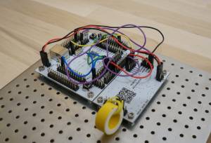
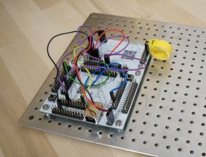
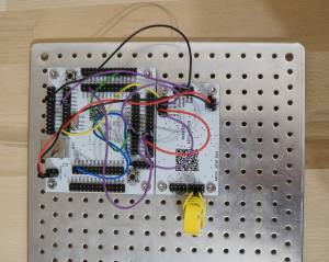
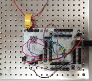
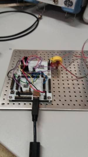
The entire device can also be built from MLAB kit modules. Specifically, it uses the AT32TQ14401A module equipped with the MCU AT32UC3A3256. This is connected to the adcaudio module, which digitizes the signal. Other modules, like the display, buttons, or I²C devices, can be connected as needed.
Firmware Compilation
AVR32 Toolchain
Download the tool package and header files from the Atmel website, for example:
- Atmel AVR 32-bit Toolchain 3.4.2 - Linux 64-bit
- Atmel AVR 8-bit and 32-bit Toolchain (3.4.2) 6.1.3.1475 - Header Files
Unpack the toolchain into the directory ~/avr32-tools. Then, place the AVR32 header files from the second package into this directory at $HOME/avr32-tools/avr32/include.
Alternatively, you can skip this step and download a preserved version of the AVR32 toolchain from MLAB Downloads.
wget http://home.mlab.cz/Downloads/Software/AVR32/avr32-tools_3.4.2.tar.bz2 ~/Download/
Then continue with the following steps:
cd ~/Download
tar -xvzf avr32-tools_3.4.2.tar.bz2
mv avr32-tools_3.4.2 $HOME/avr32-tools
export PATH=$PATH:$HOME/avr32-tools/bin
Test the functionality and version of the toolchain with:
kaklik@popelnice:~/programy/sdr-widget$ avr32-gcc --version
avr32-gcc (AVR_32_bit_GNU_Toolchain_3.4.2_435) 4.4.7
Copyright (C) 2010 Free Software Foundation, Inc.
This is free software; see the source for copying conditions.  There is NO
warranty; not even for MERCHANTABILITY or FITNESS FOR A PARTICULAR PURPOSE.
If the output is similar to the above, you can proceed with compiling the SDR-Widget.
SDR-Widget Sources
git clone  https://github.com/borgestrand/sdr-widget
cd sdr-widget/
git checkout audio-widget-experimental
Then compile the source code using the following command:
make sdr-widget
The result of the compilation will be utility programs and firmware, which will be uploaded to the MCU using the program-widget script via the dfu-programmer utility. See below.
Firmware Upload
To upload the firmware, we need a modified dfu-programmer, which we download as follows:
sudo apt-get install autotools-dev aclocal
git clone https://github.com/MLAB-project/dfu-programmer-sdr-widget.git
cd dfu-programmer-sdr-widget/
./bootstrap.sh
./configure
make
sudo make install
You can download an older compiled version of the firmware from Google Code. However, for MLAB applications, an updated version with some bug fixes is used:
wget https://github.com/MLAB-project/sdr-widget/releases/download/bolidozor-v01/widget.elf
Before running the upload script, press the BOOT button (unlabeled button, hold it down until the RESET button is pressed and released) and the RESET button on the AVR32TQ board.
sudo ./program-widget widget.elf
For any modifications, first run:
make clean
Then you can start the compilation again.
Connecting MLAB SDR-Widget Modules
For the basic SDR-Widget construction, two modules are needed:
They are interconnected as follows:
Power Supply 5V
Red, Blue
AT32TQ14401A/POWER +5V → ADCaudio01B/POWER +5V
I2S
Yellow 10cm
ADCaudio01B/MCLK → AT32TQ14401A/PC04
ADCaudio01B/BCLK → AT32TQ14401A/PX28 → AT32TQ14401A/PX34
ADCaudio01B/DOUT → AT32TQ14401A/PX25
ADCaudio01B/LRCLK → AT32TQ14401A/PX26 → AT32TQ14401A/PX36
Sample Rate Select
ADCaudio01B/OSR0 (near label) → AT32TQ14401A/PB00
ADCaudio01B/OSR1 (near label) → AT32TQ14401A/PB01
Jumper on AUDIOF0
AT32TQ14401A/JTAG2 → AT32TQ14401A/PB06
When Connecting an External Oscillator
This section describes the connection when using the ADCaudio01A module clocked by the CLKGEN01B module. If using the newer ADCaudio01B module, which has an integrated oscillator, the connection simplifies for most applications. Connecting an external oscillator is useful if you need a very stable sampling frequency, for example, for scientific experiments.
Power Supply 5V
Red, Blue
CLKGEN01B/Vcore 3.3V → ADCaudio01A/POWER +5V → AT32TQ14401A/POWER +5V
Power Supply 3.3V
Orange, Black
CLKGEN01B/POWER → TTLPECL01A/POWER → PIC16F87x/POWER
Clock Distribution
SATA cable
CLKGEN01B/CLKOUT → TTLPECL01A/PECL0
Yellow
TTLPECL01A/TTL0 → ADCaudio01A/MCLK → AT32TQ14401A/PC04
I2C
Brown
USBI2C01A/SCL → CLKGEN01B/SCL
White
USBI2C01A/SDA → CLKGEN01B/SDA
Blue
USBI2C01A/I2C GND → CLKGEN01B/POWER GND
I2S
ADCaudio01A/BCLK → AT32TQ14401A/PX28 → AT32TQ14401A/PX34
ADCaudio01A/DOUT → AT32TQ14401A/PX25
ADCaudio01A/LRCLK → AT32TQ14401A/PX26 → AT32TQ14401A/PX36
Sample Rate Select
ADCaudio01A/OSR0 (near label) → AT32TQ14401A/PB00
ADCaudio01A/OSR1 (near label) → AT32TQ14401A/PB01
Jumper on AUDIOF0
AT32TQ14401A/JTAG2 → AT32TQ14401A/PB06
SDR-Widget Configuration
The SDR-widget can be configured into several operating modes. The configuration is done using the WidgetControl.py utility. Before running it, install the necessary dependencies.
sudo apt-get install python-pythoncard python-usb
Run the configuration utility.
~/git/sdr-widget$ sudo ./WidgetControl.py
For standard use, such as inside a Bolidozor station, set the configuration as follows:
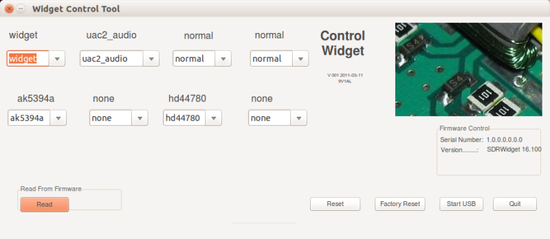
To apply the settings, disconnect and reconnect the SDR-widget to USB.
References
Testing
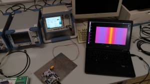
The easiest way to test the device is by connecting a signal generator to the input in the standard sound card mode. The generator's output should be connected to the balanced input of the ADC through a transformer. However, for this purpose, you can easily create one from a ferrite core taken from a switched PC power supply. A signal amplitude of a few millivolts is sufficient even with a 1:1 transformer.
The software used to display the signal from the generator can be, for example, PySDR, or you can directly use ghpsdr3.
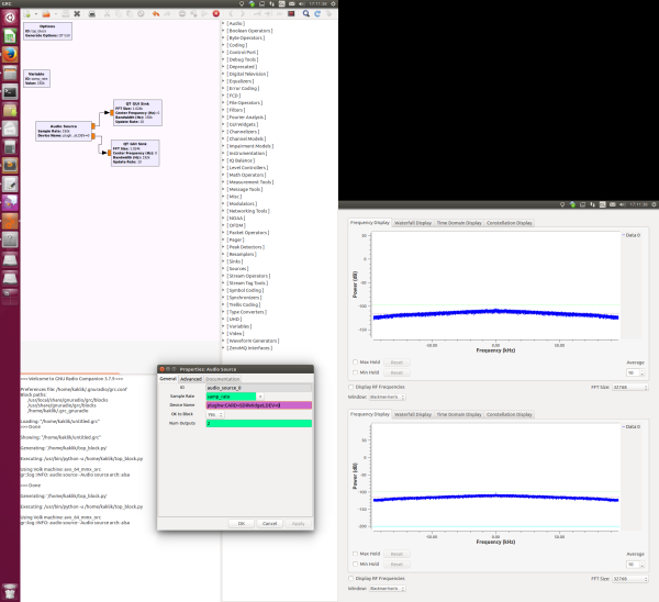
The test can also be performed without a generator using noise observable at the ADC input. The easiest display can be achieved using GNU Radio, which can be installed as follows:
sudo apt install gnuradio
Then download the test script.
svn co svn://svn.mlab.cz/MLAB/Modules/Audio/ADCaudio01B/SW/sdr-widget_test.grc
Open the test script in GNU Radio:
gnuradio-companion sdr-widget_test.grc
After running the script by pressing “Play,” the displayed spectrum should look approximately as follows.
Related Designs
The SDR-widget digitization unit, thanks to its versatility, can be used in many measurement projects and detection networks.
TODO
- Solve the issue of timestamping samples.


