Table of Contents
Software defined SDRX01B receiver
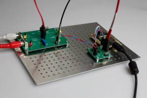
SDRX01B represents a SDR receiver originally designed to be used in amateur radioastronomy. Nevertheless, it is suitable for radioamateurs as well, for example as a radio scanner. It suits particularly well various experimental constructions, that require large variability of the system.
It differs from the other SDR receiver solutions (like SoftRock, Lima SDR, UHF SDR and others) mainly in its usability not only for radioamateur, but for radioastronomical aplications as well. Among other things, it allows for interferometric and other complex-system configuration applications, which enable complex directional signal processing (in the range of 100kHz to a minimum of 200MHz).
SDRX01B construction documentation is available on the MLAB server.
Possible applications
- Radioastronomical observations (Sun, Jupiter, Meteors, ..).
- Aircraft band communication receiver .
- Space communication / ISS / Amsat / ARISsat etc. receiver.
- Scanner for radioamateur bands.
The receiver was originally developed for applications in lower radioastronomical bands, but due to its parameters it is now widely used in other applications (for more information visit http://radio.astronomie.cz/).
The current version of the receiver can be found here: SDRX01B. SDRX01A was a test prototype, that only exists in one specimen, currently located at Úpice observatory.
Power supply
A symmetric power supply of the analog part
The analog portion of the receiver is usually fed symmetrically with +12V and -12V, currently implemented using two AC adapters connected in series. For this purpose we use the UNIPOWER02A module, that contains, except for a switch, a basic EMI filter as well.
Because of the lack of grounding in SMPS, the potential difference, sometimes as high as 100V, is created against the ground pin of the socket-outlet. It is necessary to eliminate this potential difference by connecting a ground clamp to the metal base of the receiver. Otherwise there is a risk of damage to some of the sensitive devices, such as the input LNA).
This kind of a power supply is not quite ideal, because it creates a ground loop. For sensitive applications, it is therefore recommended to use a battery or the SymPower01A module instead.
Power supply for digital part of a mixer
The digital part of the receiver contains an integrated linear stabilizer, that can be fed directly by +5V (the supply voltage stabilizes itself internally to +3.3V). The digital part is not particularly sensitive to noise produced by power supply and so it is possible to use, for example, a supply voltage form USB brought in from the frequency synthesizer.
Digitization through sound card
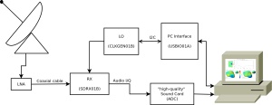
Although the SDRX01B is a software-defined receiver, the signal on its output is still analog and it must be digitized. The most simple way is to connect it with a suitable sound card. The optimal parameters of the card are following:
- Stereo input
- S/N ratio of approximately >80dB (it affects receiver's MDS and noise parameters of the whole system)
- Dynamic range >16bit (the main factor limiting the dynamic range of the system)
- Sampling rate (limits the bandwidth of the receiver) depends on the required bandwidth of the received signal. It is important to note here, that the sampling rate is directly the bandwidth (thanks to quadrature I/Q format).
Thanks to the marketing tricks used by companies, it is nowadays quite difficult to verify the parameters of modern sound cards, so we will list here the examples of external sound cards, with (by us) verified functionality.
- Creative SoundBlaster External Live! USB 24bit An external sound card with great characteristics - unfortunately no longer produced.
- Creative Sound Blaster X-Fi Surround 5.1 Pro USB A successor of the previous card, does not possess a stereo microphone, but you can use the line-input.
- BERINGHER U-CONTROL UCA222, with the obvious disadvantage of narrower bandwidth (48kHz), that is nevertheless sufficient for some applications (meteor detection). The advantage is its lower price.
Antenna connection
The SDRX01B receiver is equipped by default with a direct SMA F connector (SMA female connector for PCB), that is quite difficult to connect, for example, with a basic LW antenna. Therefore it is useful to use a reduction. An example of suitable reduction is BNC/SMA Z/V with the subsequent use of BNC/bannana connector reduction V/2xZ. It is than possible to screw in a long piece of wire (of the order of tenths to hundreds meters) or PK under the clamps. Thus equipped antenna can quite easily catch signals form a large number of short-wavelength transmitters and this configuration is the basic test of the proper function of SDRX01B receiver.
This configuration serves however only for the function verification of the system and it is not suitable for a continuous operation. See paragraph Electromagnetic interference
LO connection
The local oscillator (LO) is connected to the receiver externally using a standard SATA disc cable. For practical reasons it is recommended to use the shortest possible length of the cable. Suitable is for example a cable form Xbox 360 game console, that is approximately 10cm long and made of a very flexible material.
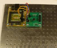
To construct the LO, the most commonly used is the CLKGEN01B module combined with a suitable microcontroller (PIC mostly). If you possess the whole MLAB receiving set, it is the following part:
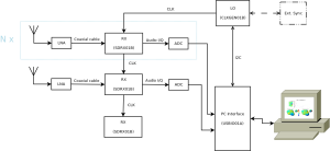
The main advantage of using the external LO lies in the possibility of sharing it among several receivers (with the help of the CLKHUB02A module). This makes it possible for all the receivers to be tuned to the same frequency with identical phase. Such setting is especially advantageous for interferometric experiments.
External LO also enables a synchronization the with the time standard, for example with the help of a GPS. Moreover, you can use multiple receivers coherently joined with just one LO.
Frequency tuning
Windows OS
Driver installation
The LO communicates with PC trough libusb libraries. After unpacking, use the “INF_wizadr” utility, that will generate the correct configuration file for LO drivers (during this procedure it is necessary to have the synthesizer connected to the computer).
Tuning utility installation
You can download and install the tuning program CFGSR with the help of automatic installer. Than, after starting the program, set the value of “multiply” (under LO tab) to 2 (the setting is for ordinary SDR receiver 4 by default) and the LO range to 10-810 MHz (affects the range of tuning).
After installing and setting the tuning program, there should be a green dot in left bottom part of the window, indicating a correct connection with Si570. The required frequency can be set in “Tune” tab.
Linux
Apart form a Windows utility CFGSR, there also exist a tool for Linux usbsoftrock. It is a more or less intuitive command-line utility.
The compilation can be executed using following commands:
sudo apt-get install libusb-dev libncurses5-dev
svn checkout http://usbsoftrock.googlecode.com/svn/trunk/ usbsoftrock-read-only
cd usbsoftrock-read-only/
./configure
make
To copy the usbsoftrock to the system use:
sudo make install
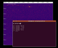
An example of log, the status of LO on Ubuntu 13.04.:
kaklik@popelnice:~/programy/usbsoftrock-read-only$ sudo ./usbsoftrock status
[sudo] password for kaklik:
Version     : 16.4
USB SerialID: TF3LJ-1.0
Startup Freq: 0.000000 (x 4.00)
Xtall Freq  : 114.225586
Smooth Tune : 3500 PPM
Si570 I2C   : 0 Hex
BPF Enabled: 1
   Band    BPF      Si570
----------  ---  -----------------
 0.0.. 9.6   0   (F - 0.00) * 1.00000
 9.6..34.0   1   (F - 0.00) * 1.00000
34.0..76.0   2   (F - 0.00) * 1.00000
76.0..       3   (F - 0.00) * 1.00000
LPF Enabled: 1
    Band    LPF
----------  ---
 0.0.. 8.0   0
 8.0..16.0   1
16.0..36.0   2
36.0..44.0   3
44.0..58.0   4
58.0..80.0   5
80.0..120.0   6
120.0..       7
kaklik@popelnice:~/programy/usbsoftrock-read-only$
Usbsoftrock also has an interactive mode, where it is possible to tune the frequency using the keyboard keys.
sudo ./usbsoftrock iteractive
In all cases, it is necessary to define the following parameters in the tuning program:
- LO multiply 2 - means, that LO would be tuned on frequency 2 times higher than the receiving frequency (for construction reasons, there is a frequency divider divide-by-2 before the receiver)
- LO range 3-810MHz - limits the range in which it is possible to tune the LO (some software, like CFGSR, has its range limited to lower frequencies, under 160MHz, because ordinary SDR receivers with similar construction do not work above these frequencies)
The LO calibration
The LO with Si570 chip set is not necessarily optimally factory-calibrated for all frequencies. It is therefore advisable to check its calibration and if necessary (when the frequency difference is too high) to recalibrate it.
The approach must bu very careful though, because in the case of unsuccessful calibration it might be required to replace the firmware in LO's MCU.
Warning! The Si570 circuit of 570ABB000107DG type has the start up frequency of 10,0MHz and in the case of calibration, it is essential to set it correctly according to default settings.
Verified software
- HDSDR (WinRAD) - A very popular Windows program for handling the SDRs. After adding the library for Si570 it enables the direct control of the LO.
- Linrad - A Linux SDR receiving tool, that contains some of the more advenced functions (that are not included in HDSDR) like mirror signal rejection in various bands
- Spectrum Lab - a utility for a various signal processing in the audible band. We mostly us it for meteor detection.
- pySDR - Our OpenGL powered waterfall software.
IQ audio support
Noise interference problems
Some users experience miscellaneous difficulties with unwanted interference during the measurements. This chapter summarizes some experiences with the most commonly occurring types of interferences and the possible solutions.
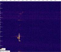
At first, let us see the picture of a correctly set receiver without the connected antenna and equipped with a “Creative Soundblaster USB External live!” sound card.
Notice the increased signal in the middle (at zero audio frequency), that is caused by the line frequency (of 50Hz) (?utility / mains ) induction in audio cables connected to the sound card. By improving the position the cables and the ground loop, further reduction is possible.
The next picture shows the case of antenna connected in relatively RF-free environment.
Now we are getting to the circumstances, when the environment surrounding the receiver is not so electromagnetically-free.
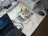
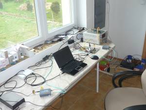
We will illustrate the problems using the assembly (shown in the picture below), that cannot be generally considered a good idea to use, if we are aiming for a minimal noise interference. The notebook with a plastic cover has a minimal capacity to attenuate the radiated energy. There are lots of AC adapters and long, poorly shielded cables on the table.
Ethernet over copper
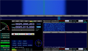
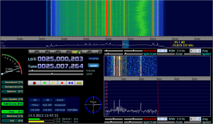
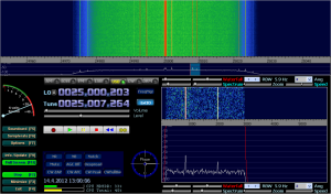
One of the most obvious reasons for interference is the switched on Ethernet. It is characterized by its thin periodic spectral lines with highest density in the region around 25MHz.
The picture below illustrates such state quite clearly:
There are more solutions to this problem, unfortunately none of them is as efficient as having the observation site completely Ethernet-free.
Shielding
The conventional UTP patch cables can be purchased as a shielded STP/FTP version as well, which than lowers the cable's radiation.
Optical Ethernet
The usage of optical Ethernet is also a viable option. Unfortunately, the present-day computers are so far not equipped with optical Ethernet ports and so it is necessary to use external Ethernet-optics convertor.
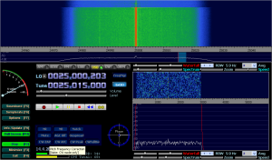
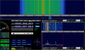
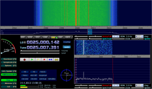
The noise interference spectrum caused by the Ethernet will change as follows:
You can see, that there are sill a lot of Ethernet caused artifacts in RF signal. They can, however, be attributed mostly to the transmission of a parasitic signal through the power cord into the same outlet, that powers the SDR receiver.
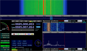
If you connect the converter to another outlet, the interference will significantly decrease in strength.
We can add a ferrite-ring to the power cord, that would further block the transmission of the RF signal through the cord.
It would certainly be possible to proceed further with similar measures. To add the ferrite to all of the cables, to separate the outlets, to enclose the receiver with a box, etc.
SMPS
FM transmitters
The measured characteristics of the receiver
Sensitivity
The MDS of -120dbm on 150MHz.
Towards the lower frequencies it increases, toward the higher it decreases.
Image frequency rejection
The minimal and easily achievable image frequency rejection is of 50dB on 150MHz RF in. The usual maximum limit is 70dB (higher values depend on the particular receiver). The image frequency rejection must be trimmed for each band separately, since it depends on detuning of the phase of mixer switching and for different frequencies the detuning can vary. The effect of a temperature on settings is not extensive and so it is possible to create a correction table for all operating bands. Some software tools (like Linarad) are able to create such table automatically after the calibration is running and proper generator is connected to the receiver's input.
Image frequency rejection settings
An interesting method involves the use of linearly modulated signal, that creates a “intensity block” in the spectrum, that is than possible to be trimmed to the minimum. Such signal can be obtained for example through FM modulation of the generator output. We've learned about this method form OK1VAW.
Electromagnetic interference
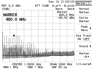
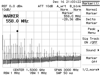
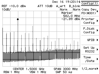
The following pictures show the spectrum of SDRXO1B emitted from the running receiver to the antenna. It is a principal effect of a switching mixer and it is the reason, why the receiver can not be operated without an insulation amplifier.
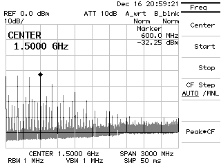
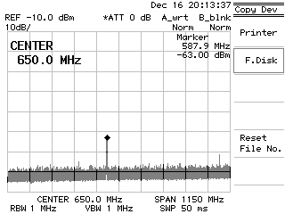
The picture below shows an improvement after the connection of LNA01A.
The measured peak is likely to be caused by the noise in the workplace (the measurements were carried out using the uncovered LNA). However, as it can be seen, the spectrum emitted from the receiver is suppressed under -70dBm limit.
FAQ
- Can I power the receiver with +/-10V? The signals on output reach amplitudes of the order of 10-100mV max. Why is than necessary to have such a wide power supply range?
The wide power supply range is necessary, because as soon as a strong signal reaches NF band, it must not cause saturation in any part of the receiver. The signal would otherwise spread to the whole output band and so it's necessary to use high dynamic range even for generally weak signals.
- Why is there no integrated voltage stabilizer? This kind of power supply makes it more complicated.
The stabilizer is missing on purpose, so that in the case of connecting more receivers (interferometry, radioastronomy) all would have the same power supply and thus the same drift.
- Do I have to power the receiver with +/-12V supply? Is the +/-10 not enough?
The receiver can be powered even with +/- 5V. If you're planing to use the receiver in a portable mode, we recommend the Li-ion batteries in pair for every branch, making the total power supply of +/- 7,4V, which should be sufficient for most applications outside the town (without strong signals). The accumulators in notebook batteries (of typical size 18650) are mostly suitable. The decreased capacity of old batteries does not matter, because the receiver's power consumption is low.
- Why does the receiver have I and Q output? Can I use the mono input of the sound card for signal digitization?
The low-frequency signal from the receiver has I/Q format, so it can include the full input high-frequency signal data. It is basically a vector format, that can be demodulated in principle by any modulation with bandwidth lower than is the bandwidth of A/D conversion. A more thorough explanation of the I/Q problem.
The examples of application
Interferometric set - the processing of coherent signals
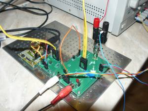
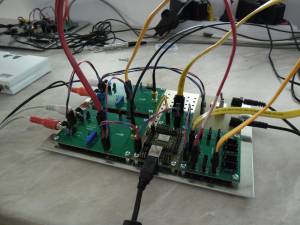
The following picture shows the first attempt to construct a radioastronomic receiver. It uses the following modules: CLKGEN01B, CLKHUB02A. The power supply is provided with two SMPSs.
The possibilities of its application are wide. The aim of the project is explained in the following article Přijímací systém pro radioastronomii.
The radioastronomy is quite perspective field for the deployment of this receiver and a large portion of research is currently devoted to it.
It's also good to point out, that amateur astronomers have a greater chance of success in the field of radio- than optic astronomy. In order to get results, radioastronomers need a lot of stations over a large area and that is easier to achieve for independent individuals than for organization. An example of a project, that supports this notion is LOFAR.
Radio meteor detection stations
The receiver is suitable for use in a radio meteor detection network, as is the case of several observatories in CR. The map of observation points. The receiver works here as a part of a radar.
You can find more detailed information on this topic on the site describing the construction of RMDS01A.
Scanner radio
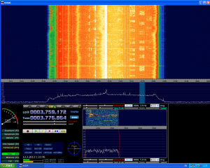
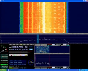
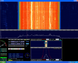
The SDR receiver can work in radioamateur bands as well. The picture below shows the example of 80m band from HDSDR program.
In the pictures you can recognize the broadcast of many LSB stations.
The telegraph portion of the band.
Ideas for improvements
To add a logarithmic scalar output indicating “the extent of the receiver's saturation”.The logarithmic detector for measuring of the integral output through the input band of the receiver. (Possibly can be done with RF detector RFdetect01A).- To add a module with a suitable ADC and so eliminate the complications with the functioning of the suitable sound card.
To design a module with a galvanically separated symmetrical power supply.Solved by SYMPOWER01A module.- To figure out a way to compare the gain between the individual receivers. (preferably digitally)
An independent receiver
Adding more modules to the arrangement could create a complete set where the receiver would be independent on a computer. Its realisation has several variants:
- The receiver with a tunable oscillator and a module with LDC that would show the tuned frequency. The buttons below the LCD would allow the retuning of the receiving frequency.
- A second variant would be the same as the first one, with an exception of digitizing the analog output, that would be transmitted through some kind of a common interface to a computer (USB, ThunderBolt, Ethernet, …). The same interface could be used for LO tuning as well.
UHF SDR SDRX02A receiver
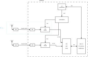
The design of the receiver described below is still only in a preliminary stage of development
The design should probably be even more modular. That includes a separate VGA input amplifier, an input band-pass filter, an I/Q demodulator with an input band-pass filter. ACD with a parallel anti-alias filter and FPGA with a parallel USB interface.
Non-coherent signal processing
Coherent signal processing
- CLKGEN01B - LO signal generator.
The coherent processing consist in the possibility of LOs synchronisation between individual stations or, in the case of using a synchronised beacon, in its potential of becoming a part of the radar system, together with the signal transmitter.
UHF SDR SDRX02B with high bandwidth
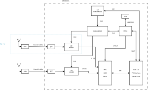
The design of the receiver described below is still only in preliminary stage of development
The design should include a separate input amplifier (VGA), an input band-pass filter to limit the possible intermodulation, an I/Q demodulator with an input band-pass filter. Analog Frond End ADC with input an anti-alias filter and FPGA with a PCIe interface for connection to the thunderbolt module.
Non-coherent signal processing
Coherent signal processing
The coherent processing consist in the possibility of LOs synchronisation between individual stations or, in the case of using a synchronised beacon, in its potential of becoming a part of the radar system, together with the signal transmitter.
References
- The Witch Navigator - an open source GNSS project of a receiver designed by FEL ČVUT.

